Description
Mu is a small standalone particle detector built for the Ogma flight computer stack at the University of Limerick's high-powered rocketry team. The idea is to put a muon detector in a rocket and see whether the count rate changes as it climbs through less atmosphere. It doesn't need the rest of the stack: it has its own battery input, onboard flash, pressure sensor, and firmware logger, so worst case it can fly as a blackbox wrapped in electrical tape.
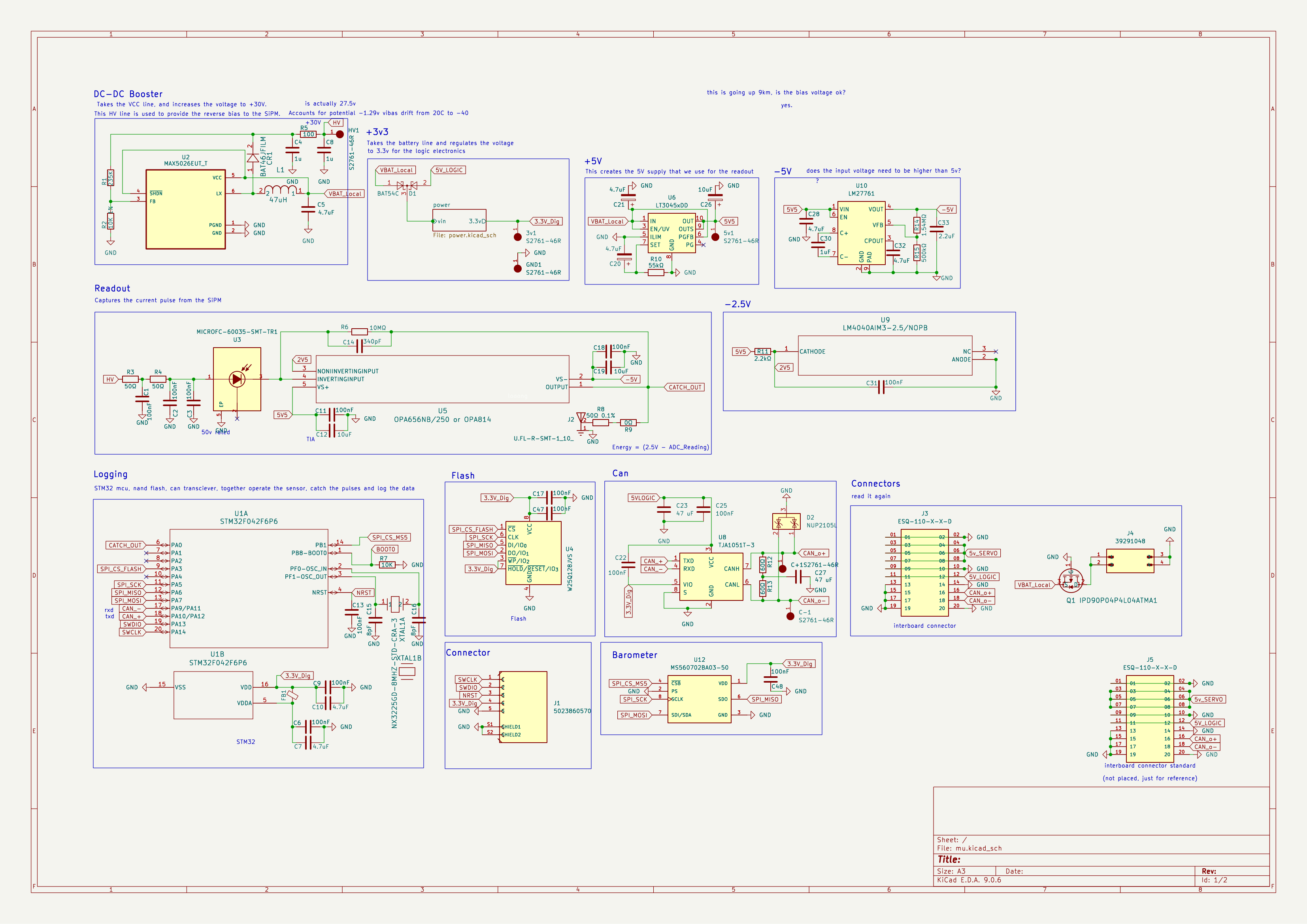
The detector is a 50x50x20mm BC-408 plastic scintillator coupled to an OnSemi MicroFC-60035 6x6mm SiPM. The SiPM is biased at about 27.5V, filtered through small 50 ohm resistors and local capacitors, then read by an OPA656/OPA814-class transimpedance stage sitting around a 2.5V virtual reference. The STM32 samples the output using ADC DMA into a circular buffer, watches for negative-going dips from the rolling baseline, and logs pulse records to flash: timestamp, baseline, amplitude, and a short waveform snapshot. It also logs MS5607 barometric pressure, temperature, and altitude once a second, so the particle data can be lined up with the flight profile afterwards.
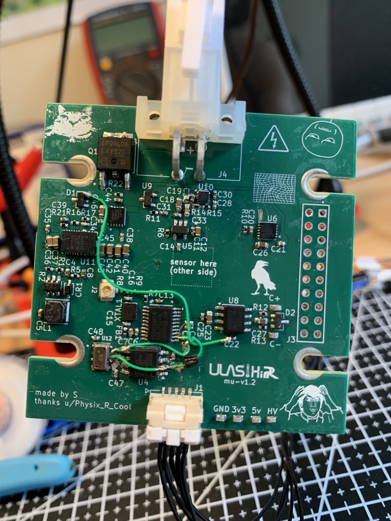
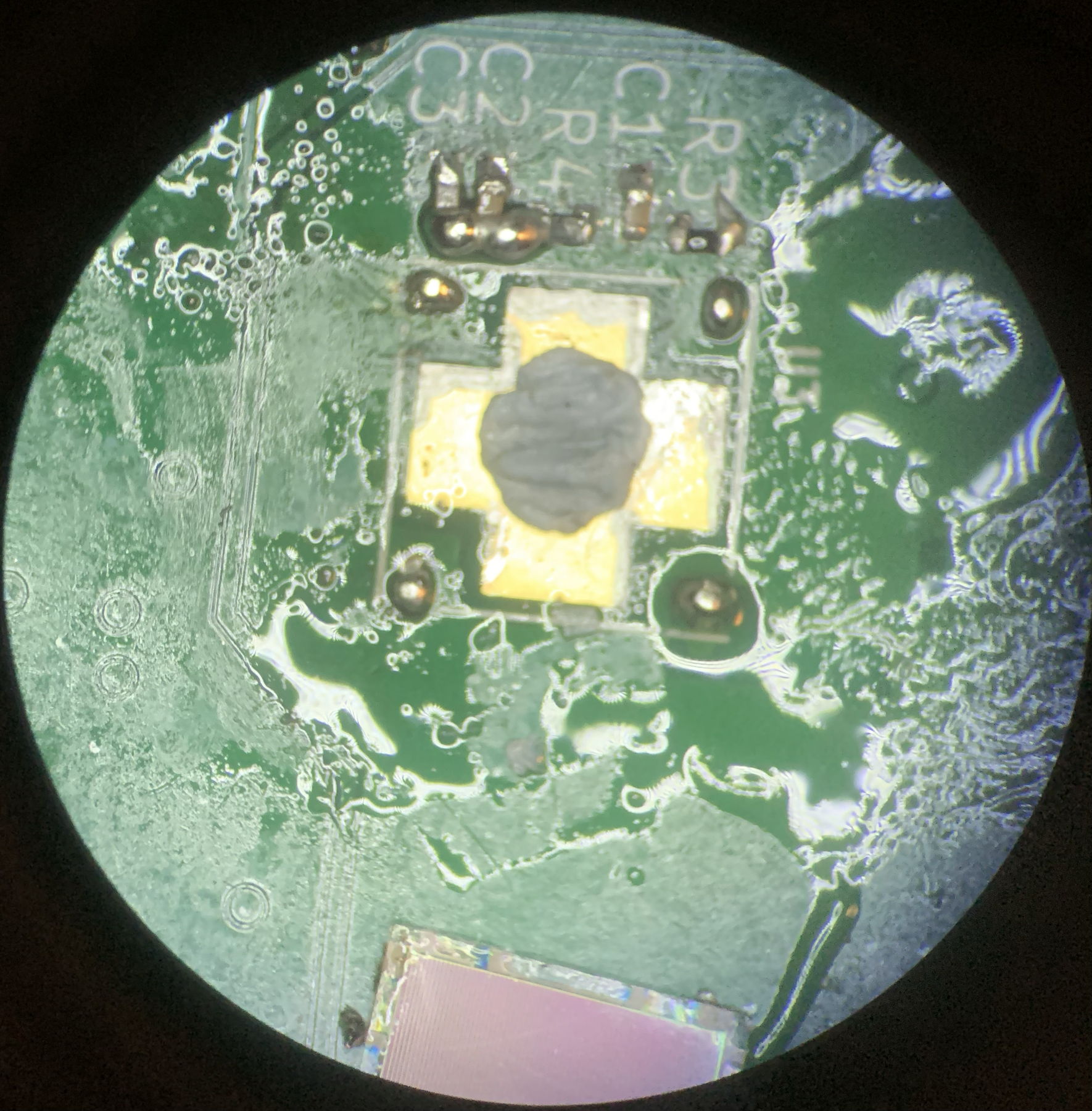
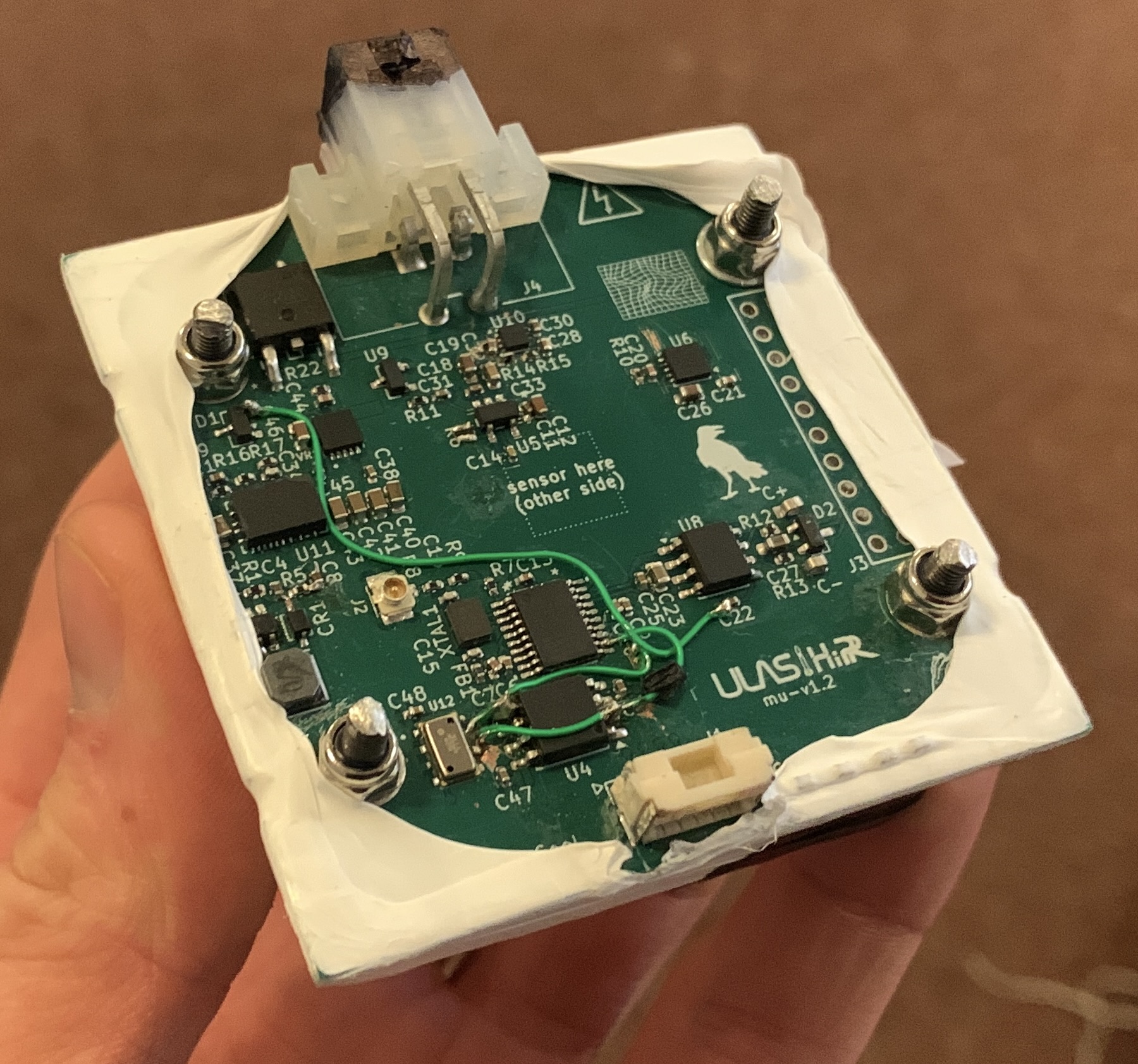
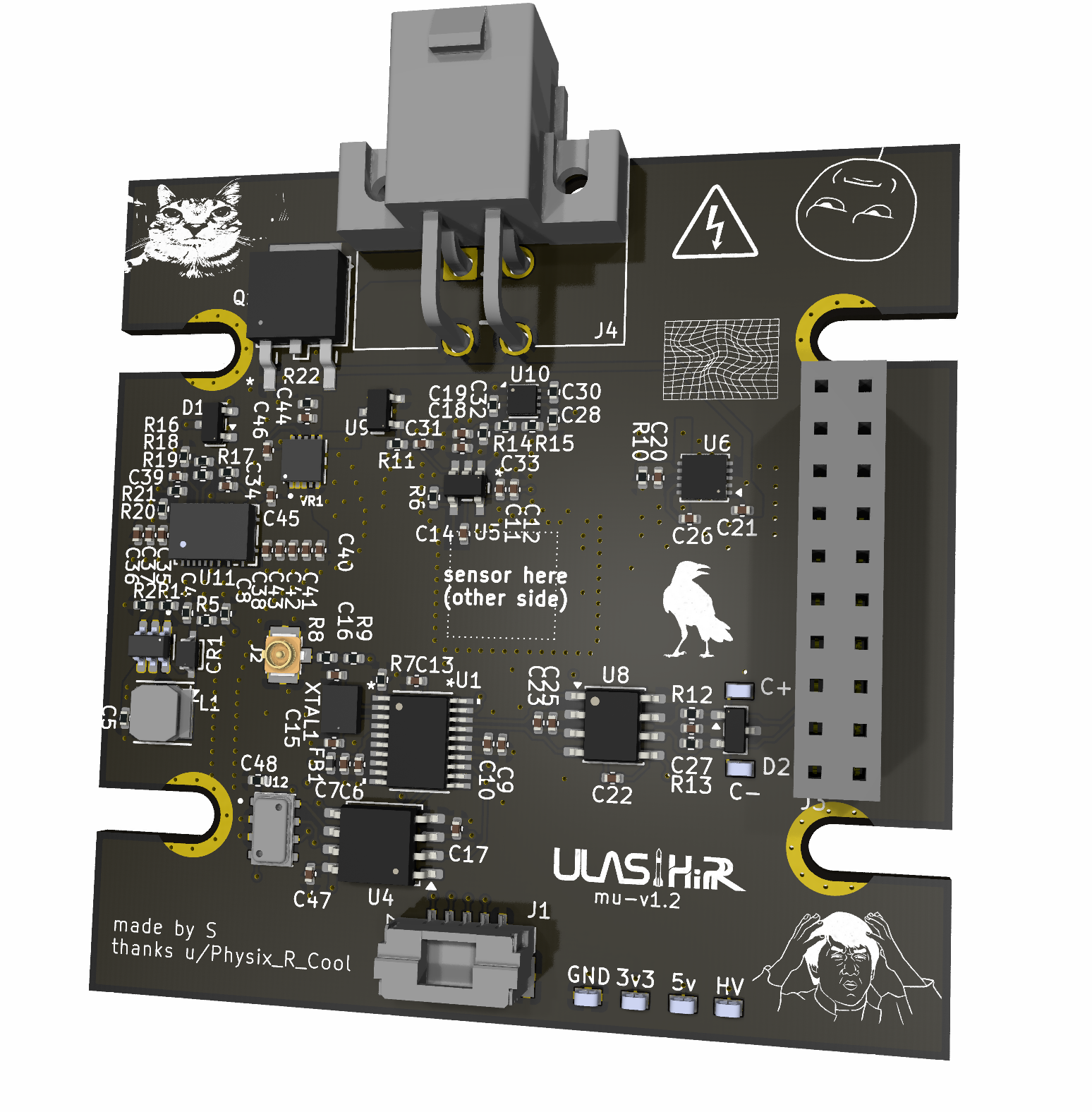
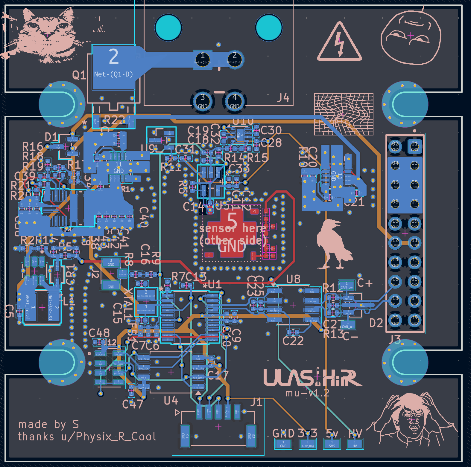
Replication warning: the Rev 1 board has the MicroFC-60035 SiPM footprint nets backwards. On an existing board, U3 must be mounted 180 degrees from the orientation indicated by the footprint's pin-1 marker. This puts SiPM pin 3 (cathode) on PCB pad 1, the filtered HV-bias node, and pin 1 (anode) on PCB pad 3, the U5 inverting-input node. Pins 2 (fast output) and 4 (no connect) then exchange two unused PCB pads.
The footprint also ties centre pad 5 to AGND, although Onsemi specifies it as no connect and recommends leaving the paddle unsoldered and floating. I got around that by putting a tiny piece of Blu Tack on the PCB beneath pad 5, keeping the centre paddle off the board, then attaching the sensor to four small solder balls around the outside. It worked, but a respin should fix the pin 1/pin 3 net mapping and leave pad 5 floating rather than preserving either workaround.
The charge-sensitive preamp was initially specced with a 10MΩ feedback resistor. After reducing that to an effective resistance of roughly 264kΩ, the 330pF feedback capacitor set a decay time constant of about 87µs. The flight firmware samples every 10µs, so it can read the stretched pulse rather than trying to catch the original nanosecond event.
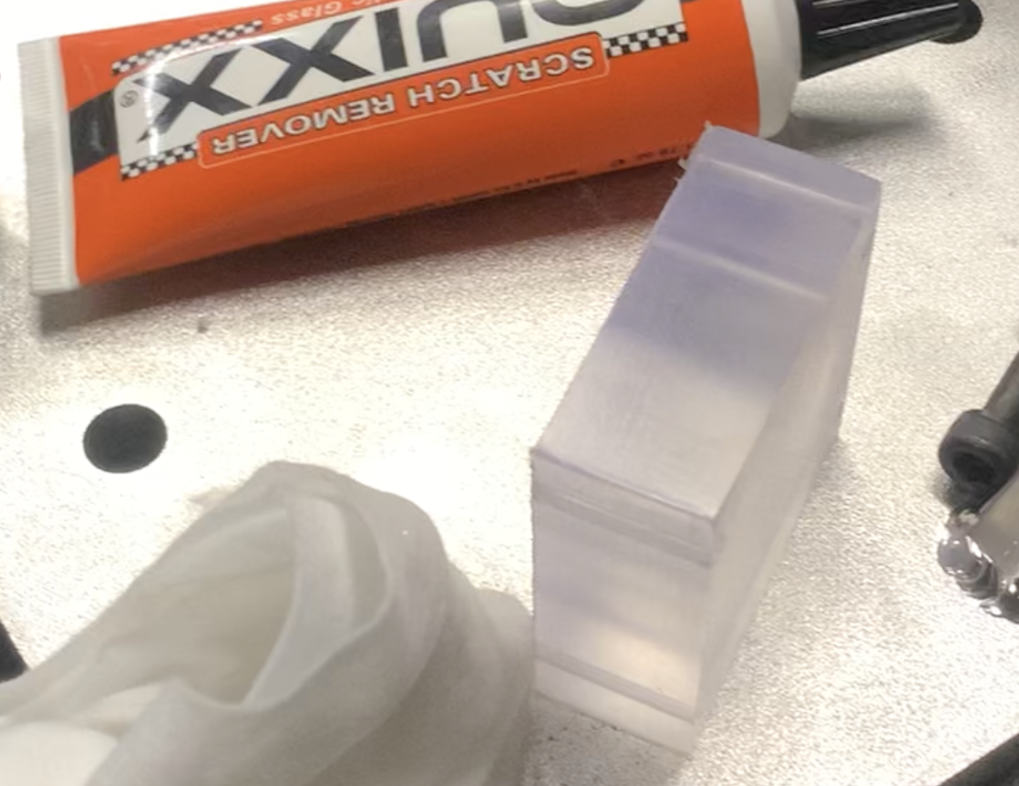
I reached out to Fabien Dubar at Luxium Solutions, who generously sponsored two 50x50x50mm cubes of BC-408 scintillating plastic. I cut the 50x50x20mm detector from one of them using the tools in the University of Limerick's workshop, then polished it using acrylic scratch remover that one of the lab technicians found. Stephen Bellis, a former onsemi Principal Engineer, also gave me advice on the readout circuit in the initial stages. I am grateful to both of them for their support. Mu's Rev 1 PCB was generously sponsored through EasyEDA Education, with Domenico (Dom) Qin arranging the support, and manufactured by JLCPCB.
I posted our initial schematic and PCB designs onto r/PCB with Ogma, then posted a final Mu review. Within 2 reviews of being confidently incorrect, u/Physix_R_Cool reached out with a proven TIA schematic and layout that he had used for his own SiPM projects, including at ISOLDE at CERN. He pointed out that our non-inverting OPA656 stage would delete the 5ns pulse rather than stretch it, then sent us the board files, real pulse captures, and advice on polishing, wrapping, and optically coupling the scintillator. He was also very clear that the TIA design wasn't his, he had just used it and knew it worked.
Progress
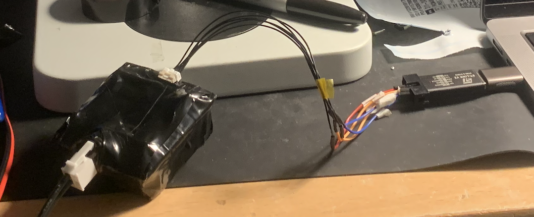
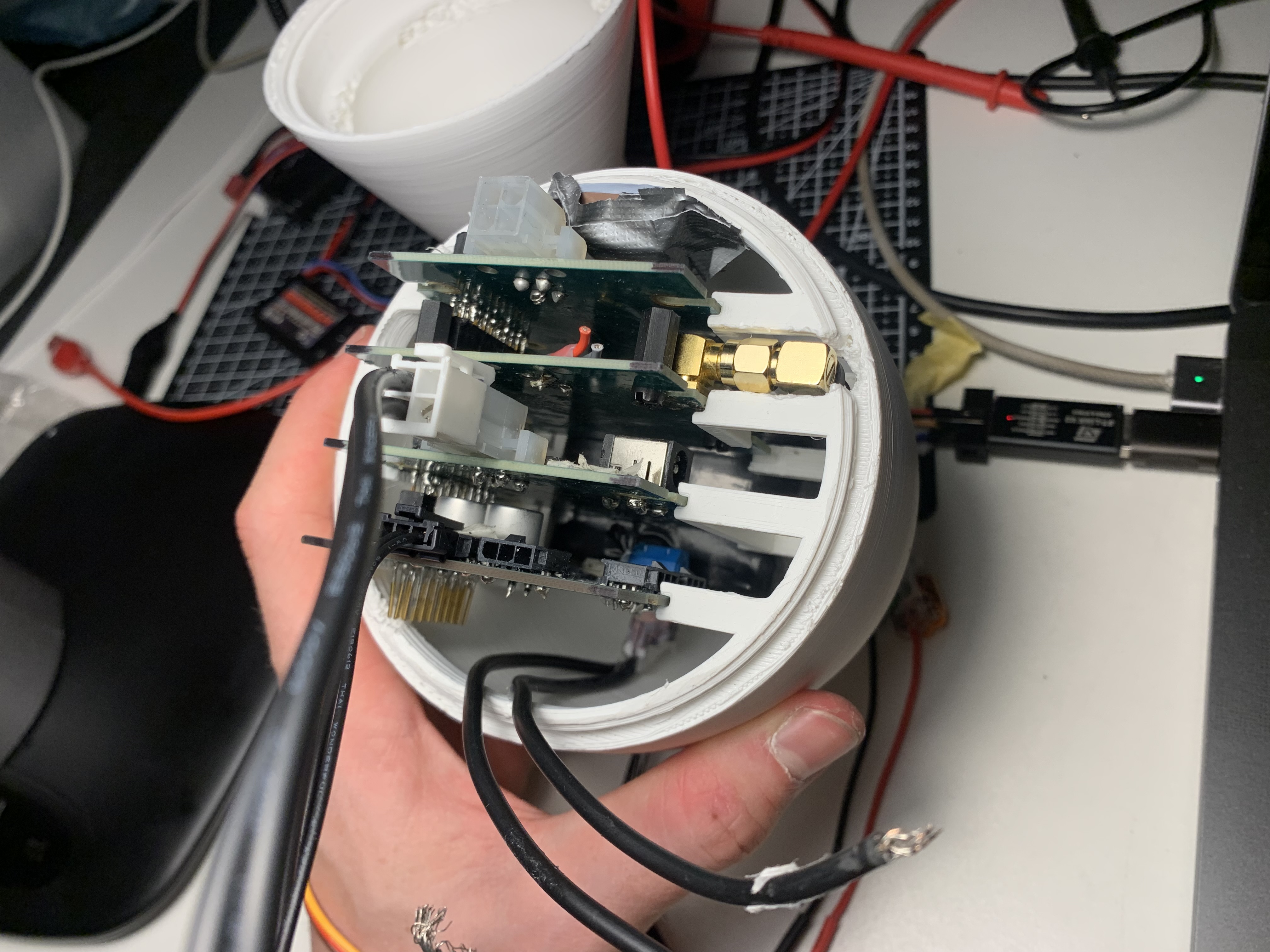
The schematic was only half the work. The physical detector fought back constantly. SiPMs are absurdly sensitive, so small light leaks through bolt holes, washers, and even the translucent Molex battery connector were enough to saturate the readout. At one point the board sat at a normal ~48mA in darkness and jumped to 200mA under a microscope light. Covering one spot with my finger fixed it, so it wasn't an analogue instability, just light getting in through gaps in the tape on the opposite side of the board.
Two nights before Mach26 (Scottish competition), in my student accommodation, I filed down the four mounting bolts into a wastebin because light was leaking in around them. They had to be short enough to fully cover. I also coloured in the Molex battery connector with a black Sharpie, because the plastic was just translucent enough to act as a tiny window.
The first version of the feedback network was also way too optimistic. We had specced a feedback resistor of 10MΩ. With the real dark current of a 6x6mm SiPM, the high feedback resistance let the amplifier pull the baseline down toward the negative rail. I added shunt feedback resistors, bringing the effective feedback resistance down to roughly 264kΩ, which kept the baseline inside the STM32's ADC range instead of relying on the MCU's clamp diodes to survive it.
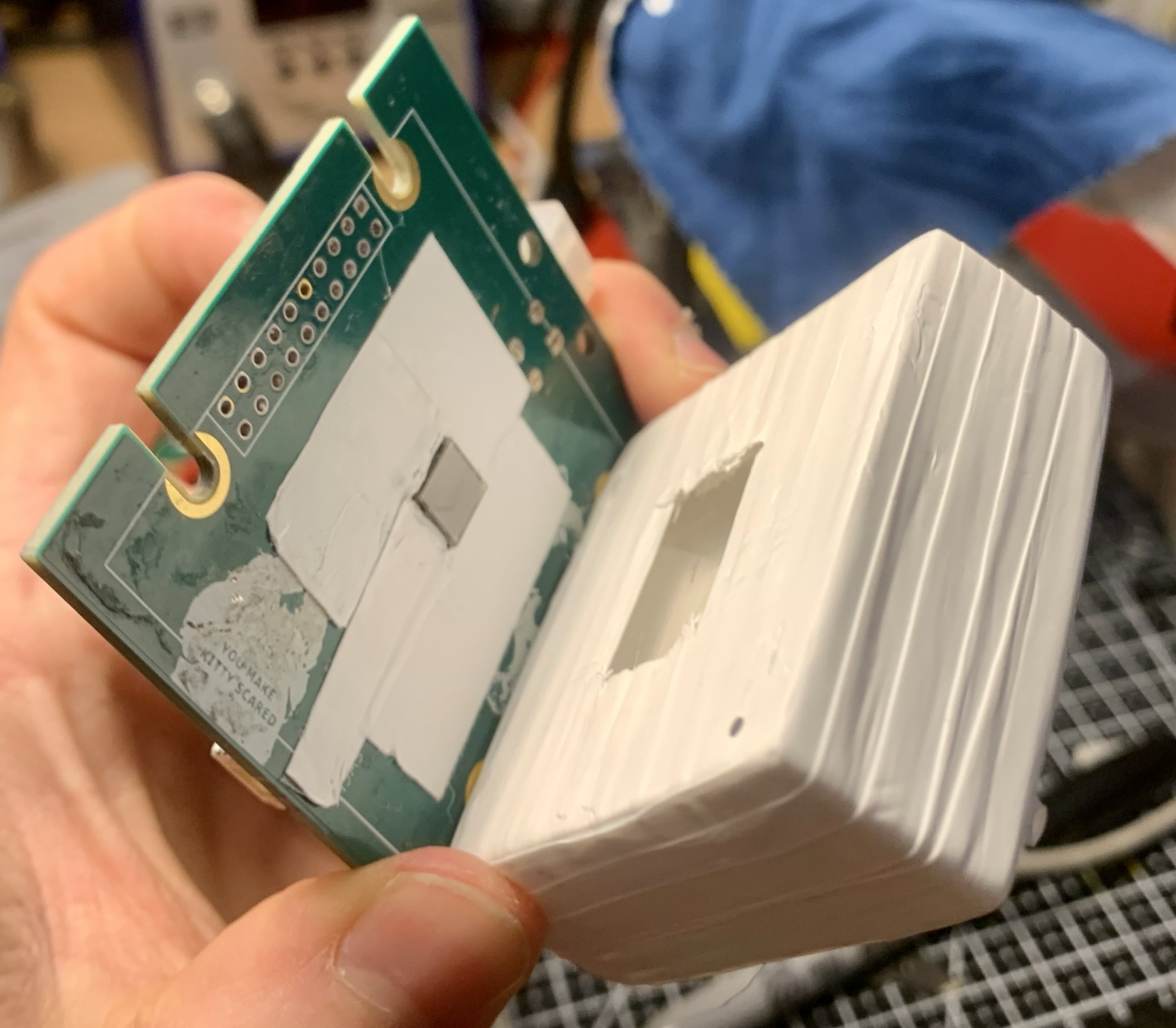
I had a couple board-level mistakes too. I had to reroute the SPI data lines after swapping them, and because the flash and MS5607 shared the same bus, fixing one meant flipping the other. Assembly was a hands-on optics problem: file the mounting bolts, reseat the crystal, wrap the scintillator in PTFE tape†, wrap the whole thing in electrical tape, test it, find another leak, repeat. I also added some needle pin holes for accurate barometric pressure readings.
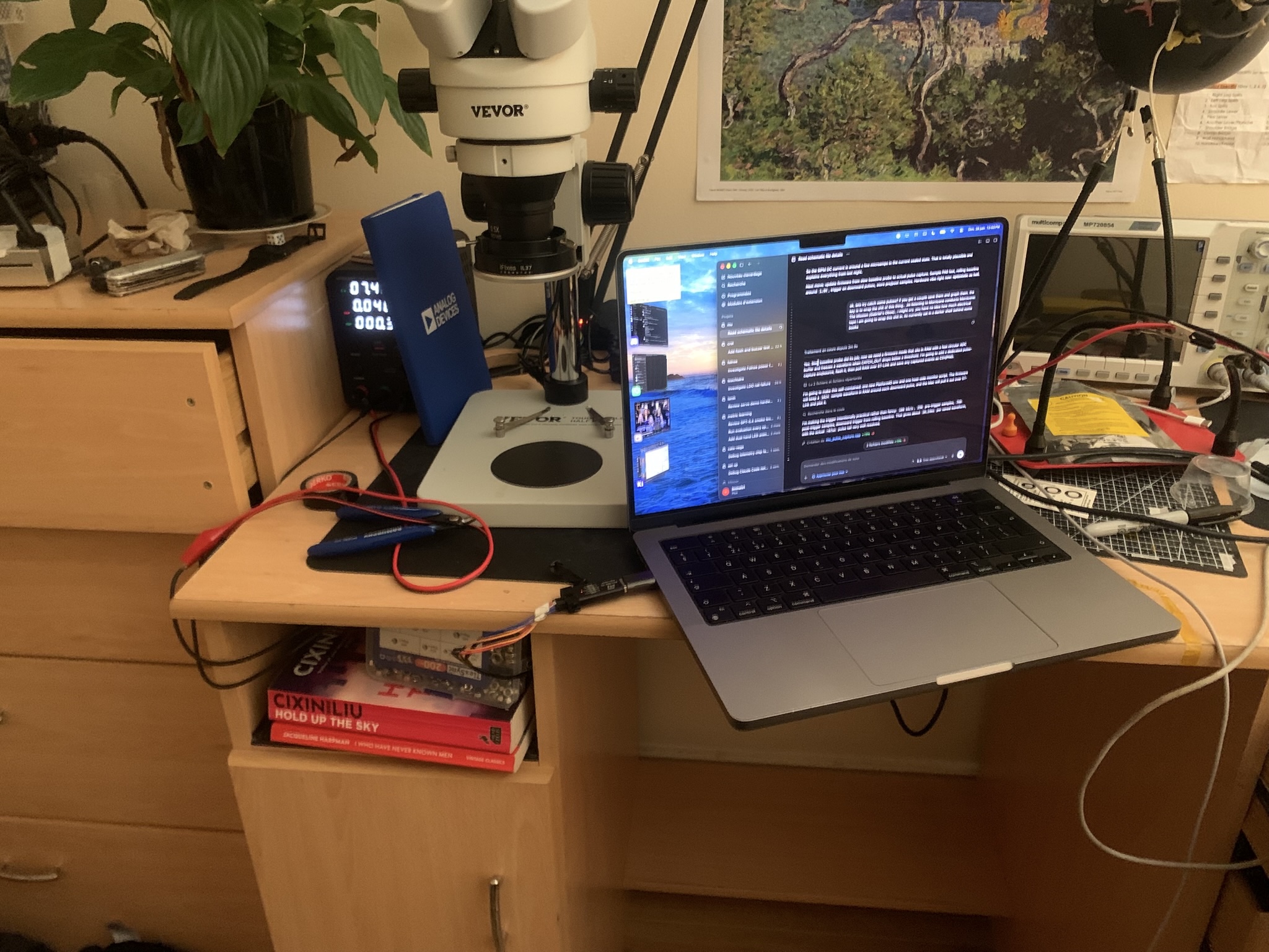
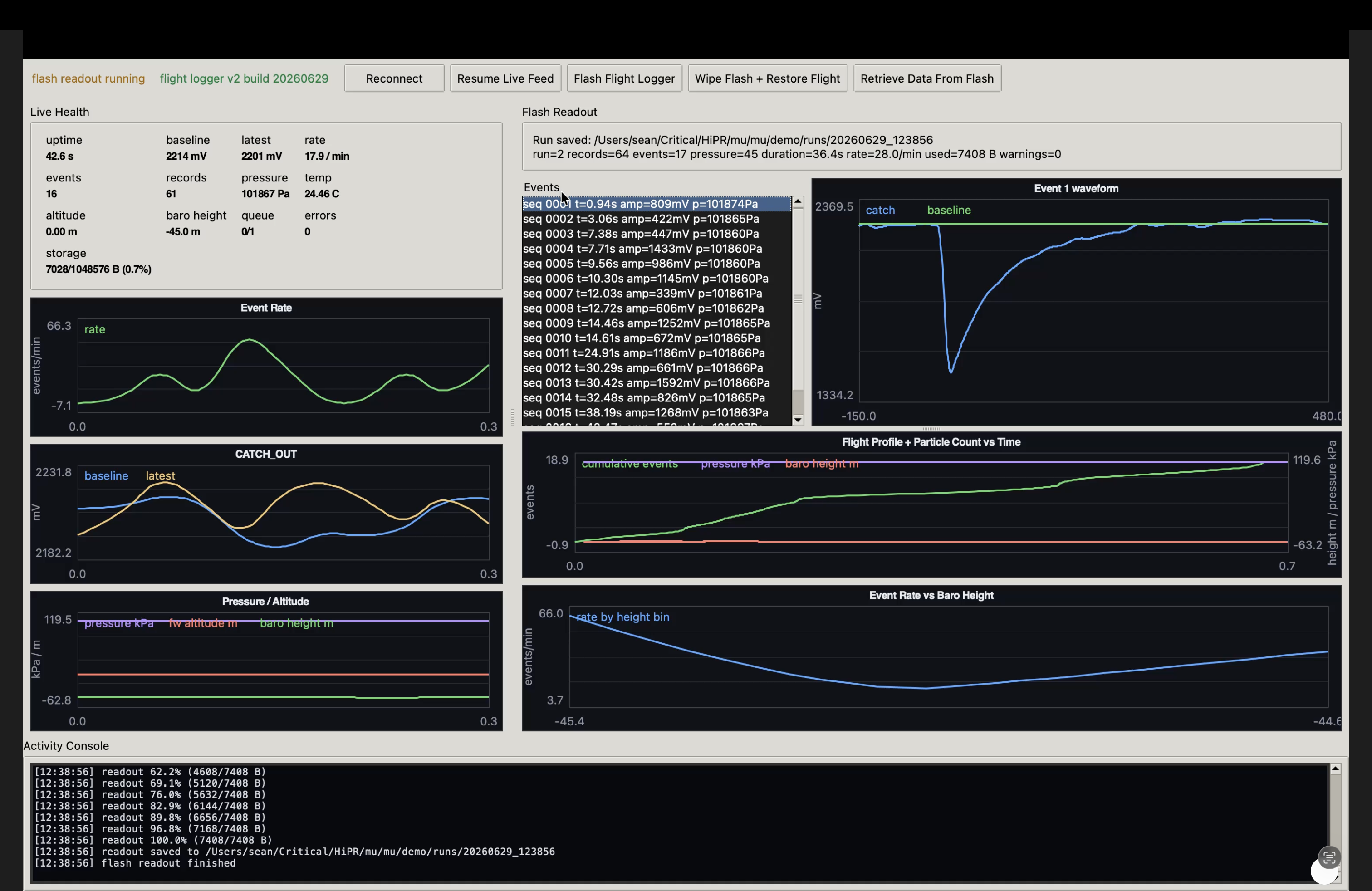
The first real capture was great craic. I had Mu hidden behind a stack of books in a shallow opening under my desk, sitting on top of some black plastic ribs that were once used to store CD cases. It started recording clean negative-going charge pulses, around 18-31 events per minute across a few sessions, fairly close to the rough 25/min estimate for that scintillator area at sea level. I did not use any sort of optical coupling fluid, and I was very concerned about this (and I tried to source some the week before). After I calmed down, I celebrated by starting to play Zelda: Breath of the Wild at my roommate's offer.
I tested it a handful more times and found an issue where, on battery power, it tried initialising the flash immediately at boot and of course that would fail, so it wouldn't log. It now retries a handful of times at boot and works.
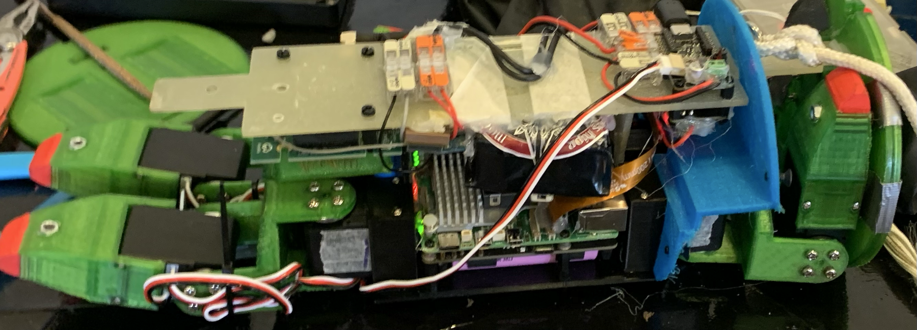
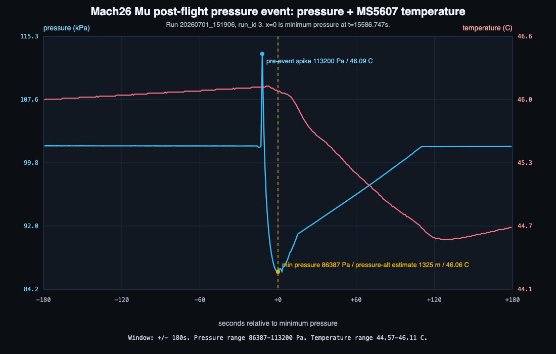
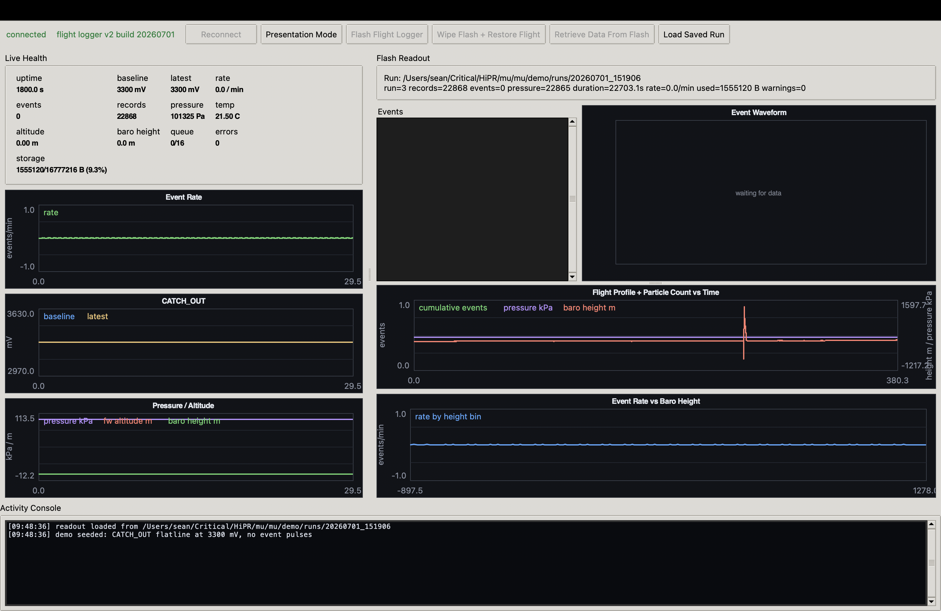
It didn't get a clean run at Mach26. Mu sat close to a Raspberry Pi 5 heatsink, but the stored MS5607 data later put the minimum-pressure period at about 46°C, not the roughly 70°C I first remembered. Afterward I could reproduce the failure by tightening and loosening the crystal screws: too much pressure bent the board and shorted the detector stack. Heat may have contributed through expansion, but the flight data does not prove that. After reseating the detector and repairing the disturbed analogue parts, Mu came back.
On 15 August 2026, Mu flew again as a standalone payload beside Ogma. Its pressure logger survived and recorded the full flight. The particle channel had already been quiet for 53.603 minutes of logged prelaunch time. The flight evidence is below.
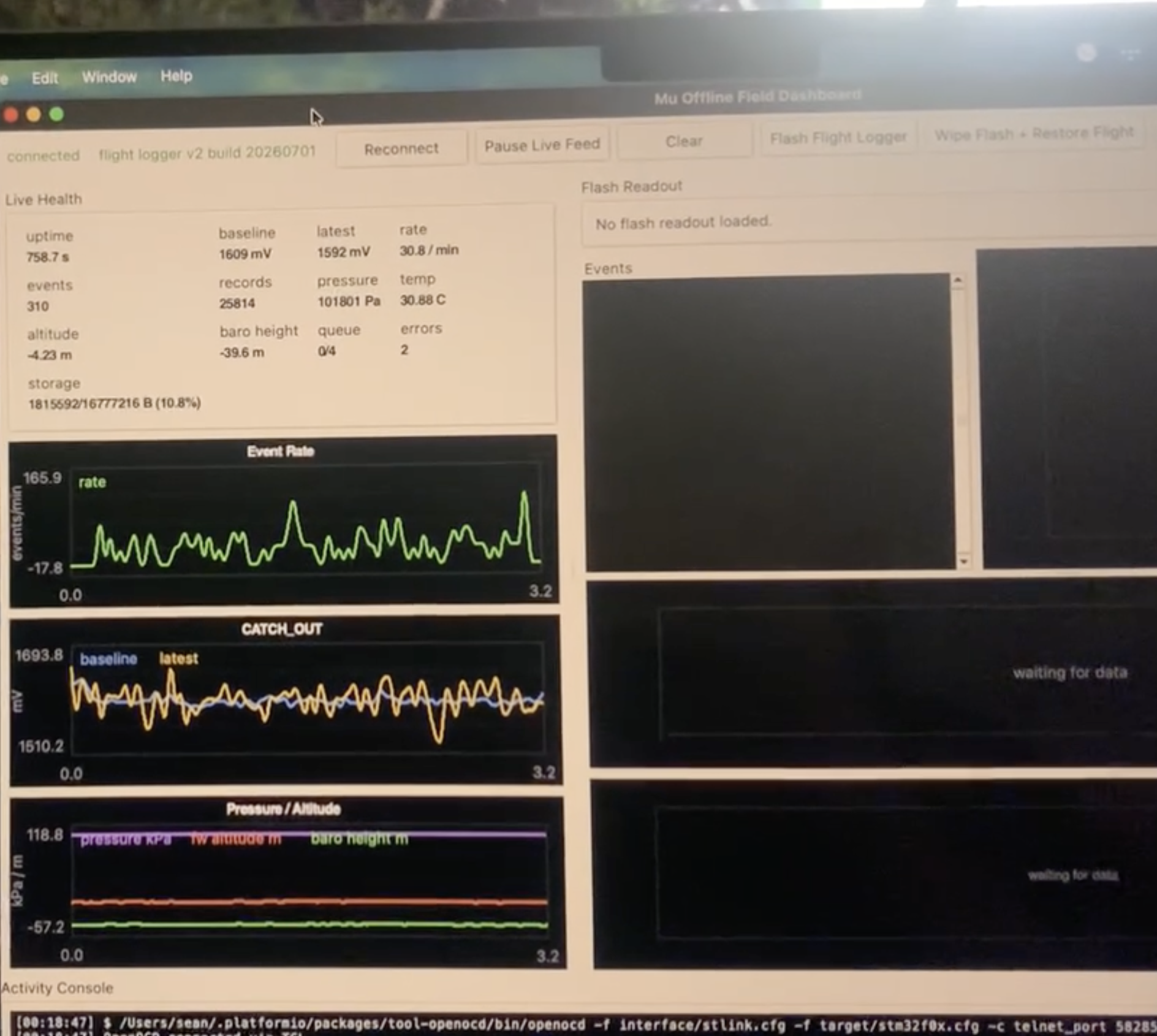
I also wrote the Python field console used to work with Mu. It can flash new firmware, read named blocks of the STM32's SRAM over SWD for live plots, and retrieve the external flash log through a 512-byte SRAM mailbox in contiguous chunks for local parsing and plotting.
† And then cut the window out, rather than just including the opening in the wrapping. The latter resulted in uneven wrapping.
Documentation
Repo: Mu.