Description
Pace is a small timer I made after our pool closed, when I was still a competitive swimmer and wanted a way to keep pace while training alone.
In swimming it's hard to gauge how fast you are actually moving when you don't have someone to pace yourself against. There is the minute clock on the wall but you can only see that at the wall or during a breath. I wanted something that I could race against.
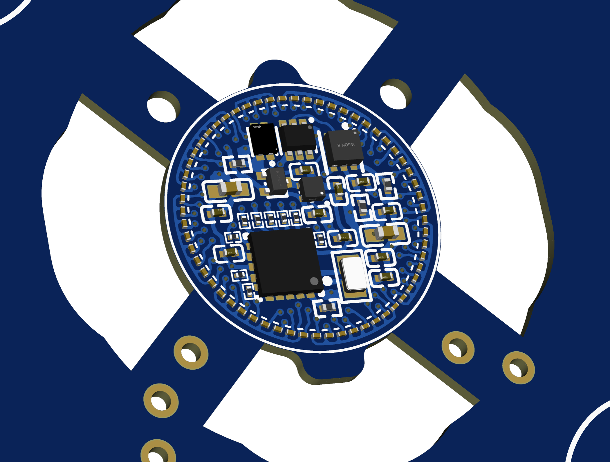
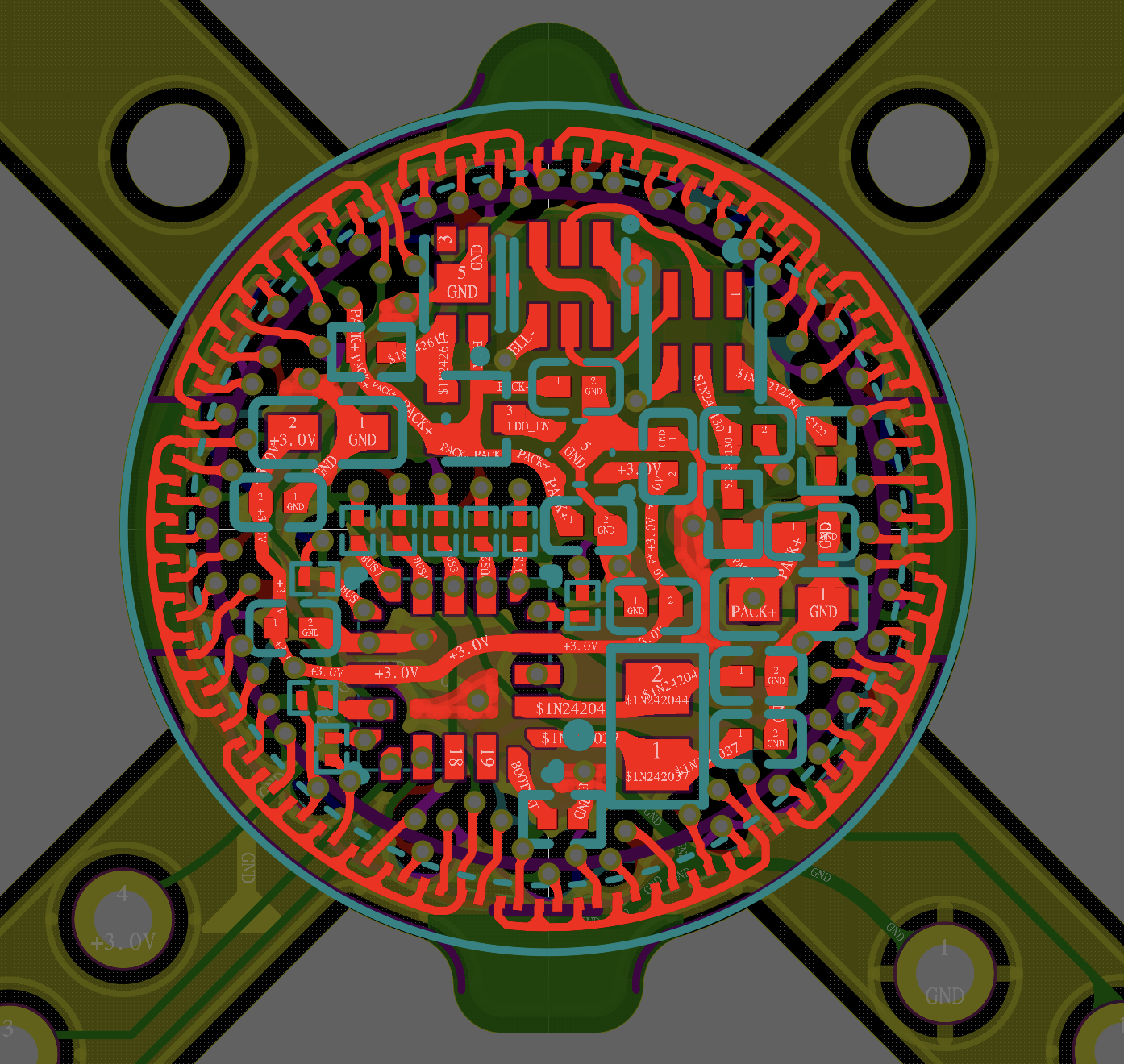
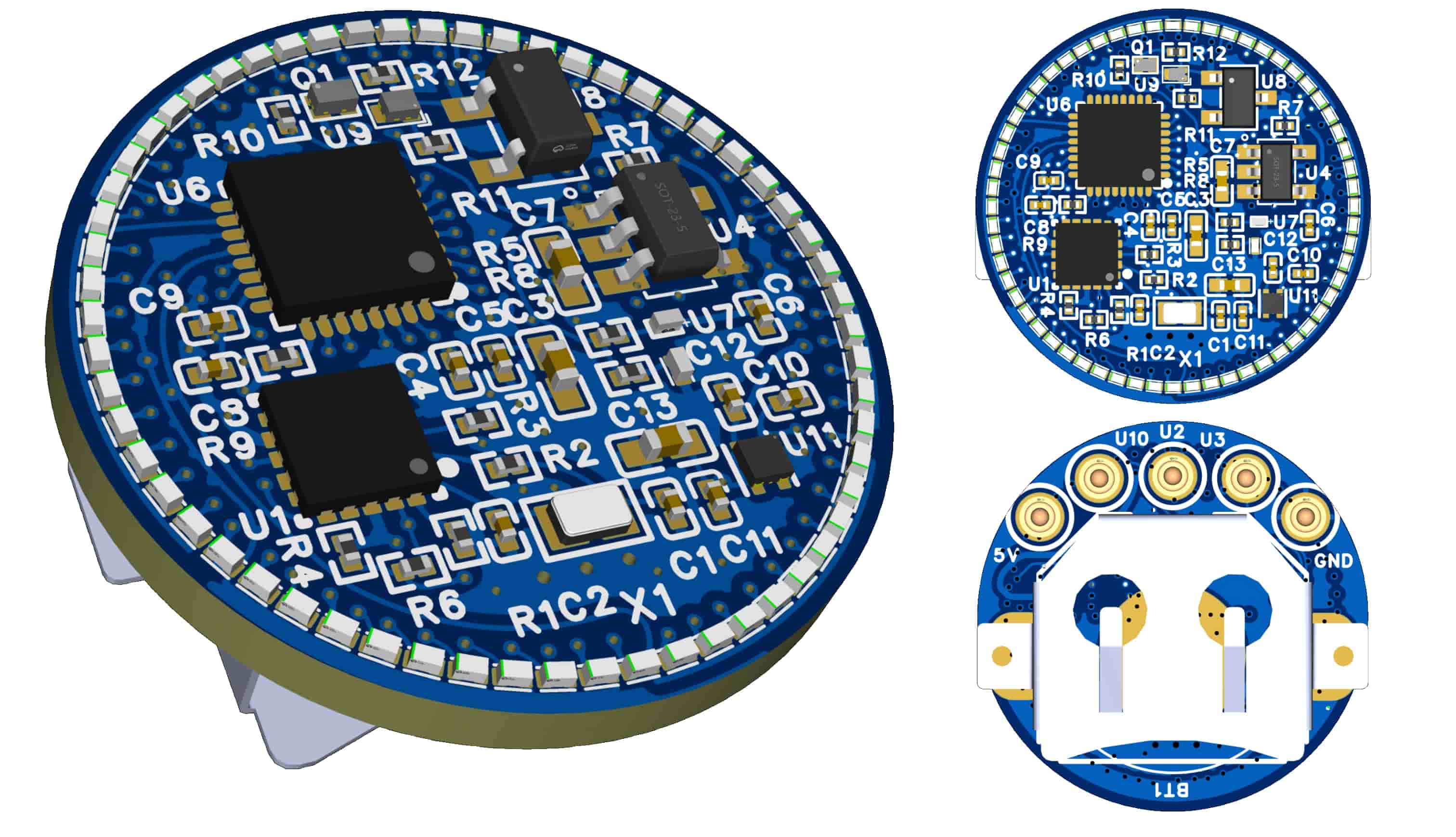
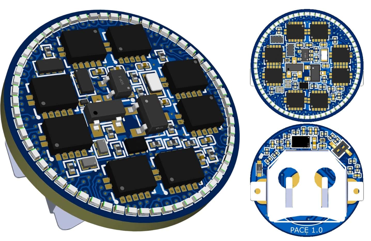
The eight-layer PCB is smaller than a euro one-cent coin, at 13mm diameter. A ferrous disc on the back lets it sit on glasses or swimming goggles when you put a magnet on the other side of the lens. The magnet also activates it.
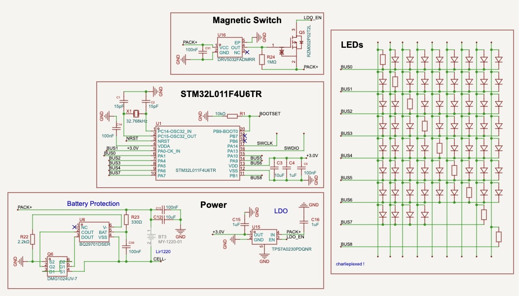
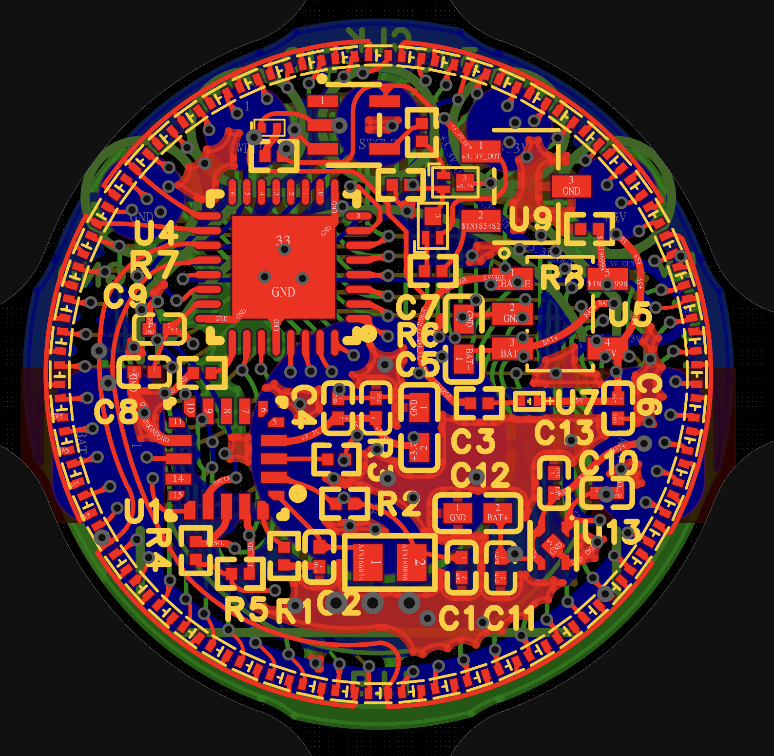
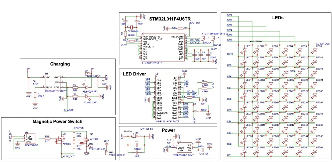
Sixty LEDs run around the edge. A seconds hand moves one position every second, a minute hand advances after each full sixty-second revolution, and a fixed marker at the top of the ring keeps the display readable. The quarter marks are yellow and the other LEDs are green. The STM32L0 charlieplexes the ring across nine GPIO lines, switching between LEDs in one-millisecond slices. The hands and marker appear together, while the tiny rechargeable coin cell powers only one LED at a time.
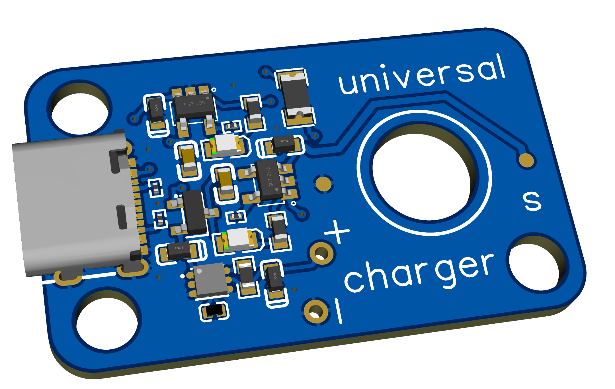
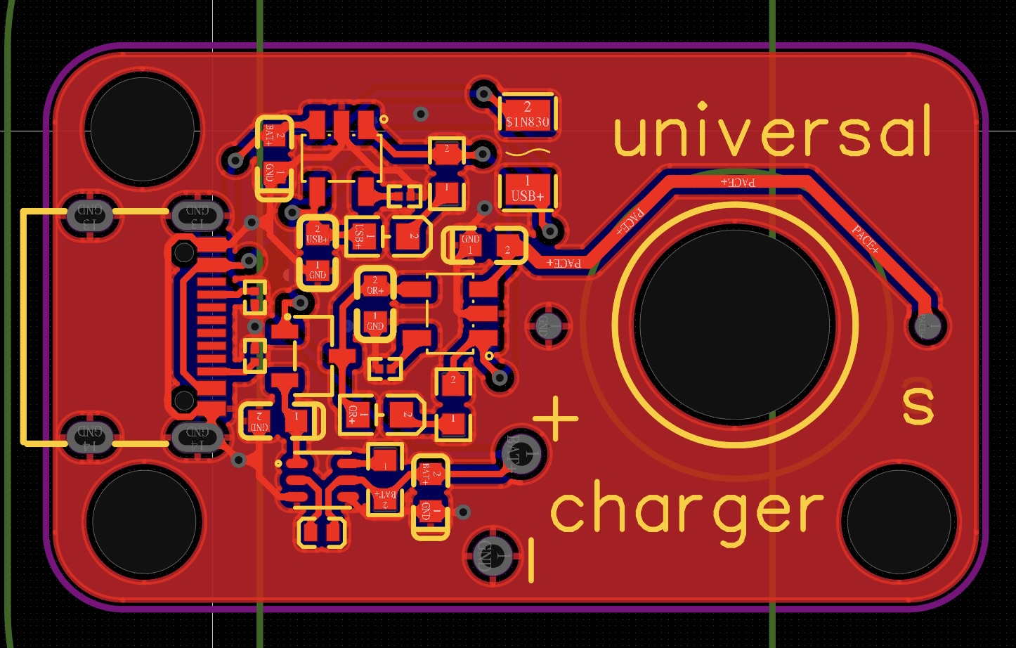
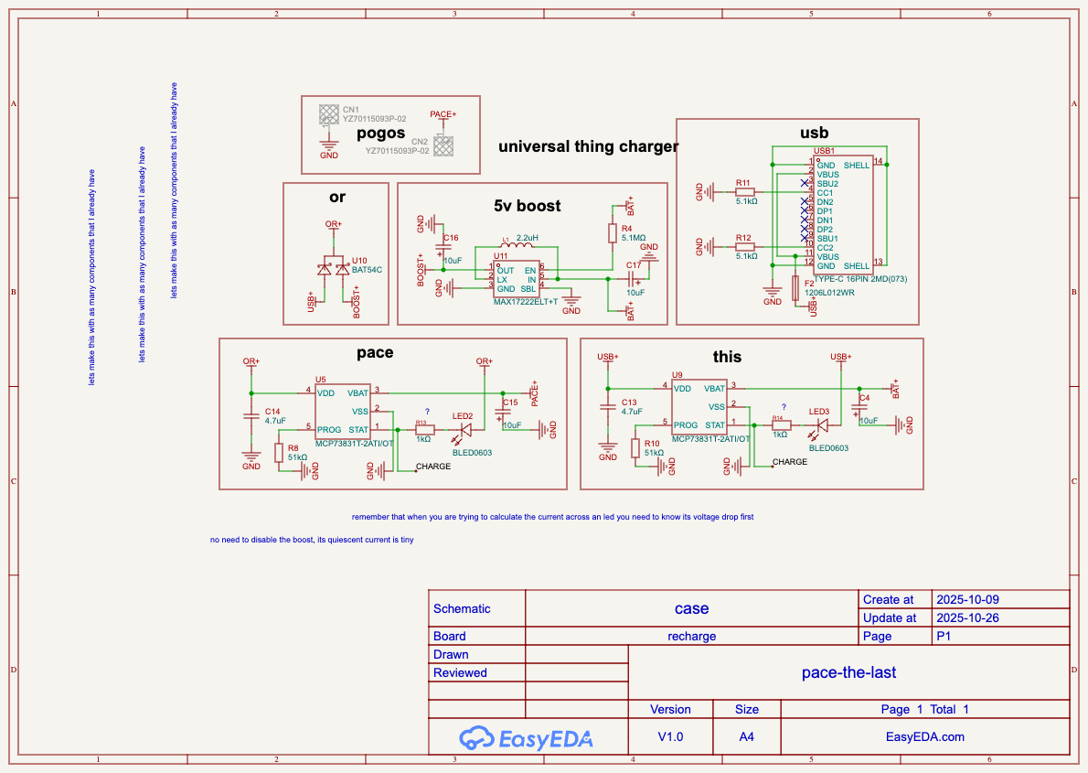
Pace lives in a printed charging case with its own battery and USB-C input. Two spring-loaded pogo contacts meet the charging pads on the timer. The assembled case now charges Pace with the magnetic lid closed.
I've tested Pace on both glasses and goggles during dry-land exercise, including dead hangs. This version isn't waterproof, so I haven't used it in a pool. What surprised me was how the display faded into my awareness, giving me something to pace against without needing to consciously read the time.
Build
The first two boards
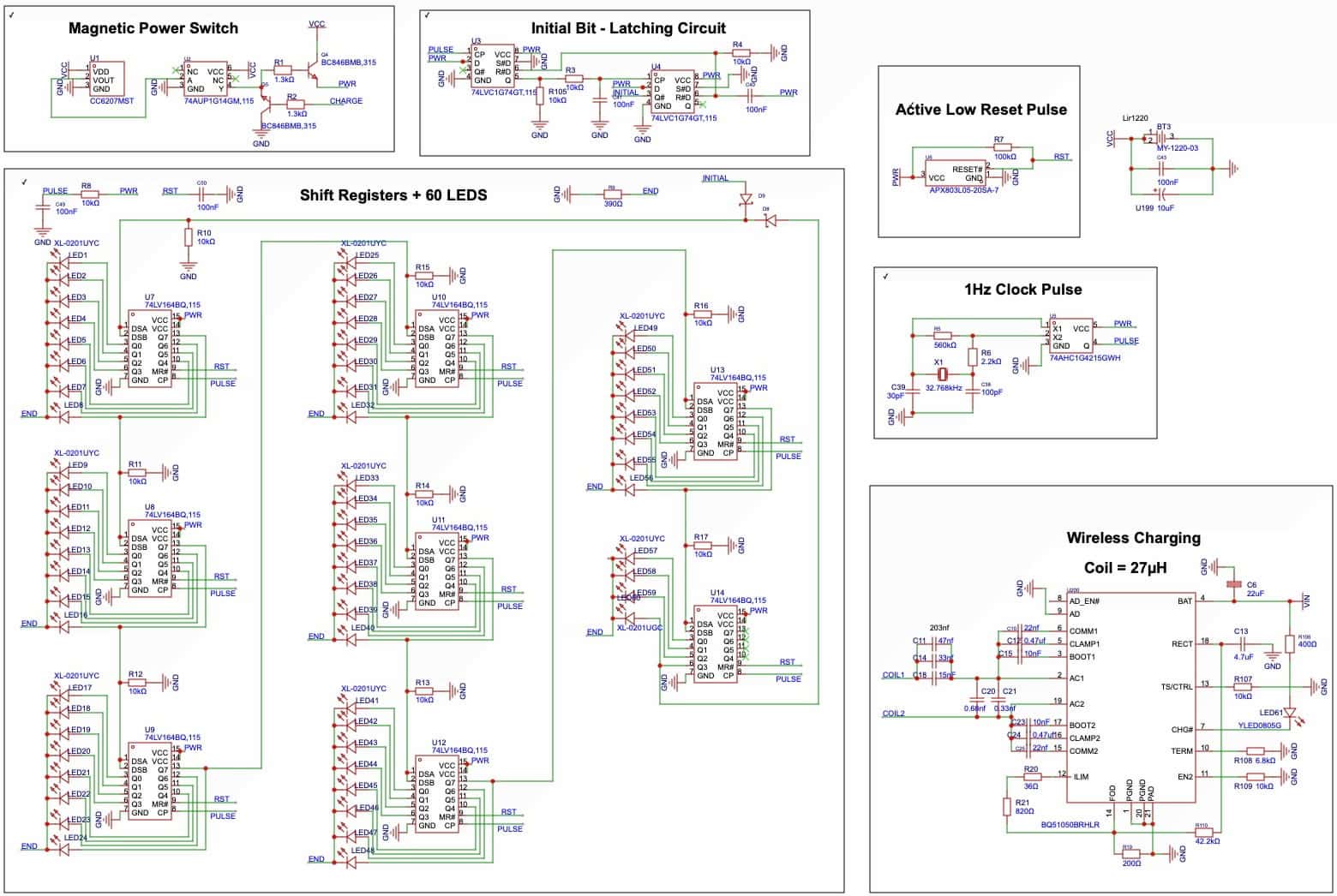
I started Pace towards the end of the Patch Summer Accelerator in 2024, in the summer before my Leaving Cert. V1 used eight daisy-chained shift registers, a quartz oscillator, and a delayed latching circuit to inject the first bit. It was an elaborate way to move one light around a ring. I posted it on Reddit, got a fairly blunt review, and moved to an STM32 and LED matrix driver for v2.
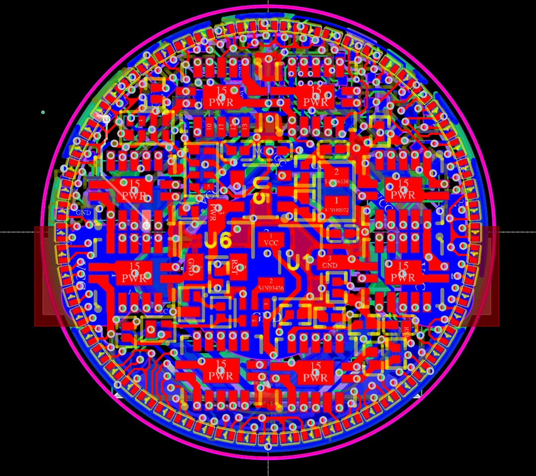
The second review was kinder. One comment said, “It's a truly beautiful board layout. I hope it works!” Another immediately asked, “What will happen if battery voltage drops under 3.4ish?” Both were fair. That board reached the point of ordering before I realised its buried vias would add about €500. I never ordered it.
The project sat for a while. In October 2025, once I had the space, I came back to finish it. I rebuilt the main board, charge board, case, and firmware. Charlieplexing let me remove the external matrix driver and route sixty LEDs across nine bus lines. The final board still needed eight layers, but the buried-via design was gone.
Turning an Ender 3 into a placement machine
The LEDs are 01005 parts, 0.4 × 0.2mm. Before assembling the board I practised with spare components and a blunt 30-gauge needle. I could pick them up through friction alone. I could also lose them, find them, and lose them again several times before they finally disappeared.
I tried to make the placement less dependent on my hands by converting an Ender 3 into a manually controlled pick-and-place machine. I made a Python control interface to send movement commands over USB and printed a holder for the syringe and needle. The syringe rested on its shoulders in the holder so I could rotate it by hand. For the smallest parts I intended to keep using friction; vacuum pickup, powered syringe control, and a camera on the head were ideas for extending it.
The controls worked. I could jog X, Y, and Z from the keyboard and select steps down to a commanded 0.01mm, though I never measured the actual placement accuracy. I went through bracket revisions, camera tests, and a nearly broken holder reinforced with superglue and bicarbonate. A webcam would not focus usefully on the work. A phone camera gave me an image, but still did not give me a workable view of the needle meeting the pads.
The harder problem was getting my eyes into the machine. At one point I was lying on a yoga mat inside the printer enclosure, trying to see the board with side lighting. I moved the printer onto the desk and tried again with the board on glass and loupes pushed out in front of my face. Then I used my helping hands set to hold a sheet of aluminium as a raised platform for the PCB, bringing it up to eye level. It was very finicky. I could pick parts up through friction, but judging the depth was difficult with my lazy eye. A USB microscope might be worth trying if I do this again.
By the afternoon of 23 November I had given up on the printer. I cleaned the board and redid the paste for hand placement.
Hand assembly, then undoing bits of it
I taped all six loupes in the box together for roughly 10× magnification and hunched over my little IKEA desk in shrimp posture, wrists anchored on the table. Yuki Hayashi's At the Limit played on loop for about seven hours. I picked up and positioned the LEDs with the blunt needle.†
The sixty LEDs were in place just after midnight on 24 November. While working on the remaining components, I flicked a resistor and knocked six LEDs out of position. I repaired the paste deposits and replaced the displaced parts. Placement and rework carried on into the morning, then I reflowed the board in the oven I had built from a halogen floodlamp.
It looked excellent coming out. Then I noticed that I had placed the STM32 ninety degrees wrong.
I had to rework the controller's orientation before I could test the board. I got help from the electronics department with that repair on 26 November. Once I could run the display, a large part of the ring still did not light. I initially wondered whether I had a mapping or firmware problem because some of the missing positions looked patterned. Seeing solder under magnification had not told me whether the joints actually conducted.
The paste had sat out through a long placement session. My explanation at the time was that it had dried out and lost flux activity, leaving poor wetting and what I described as head-in-pillow joints. Later heating with fresh flux made a substantial difference. On 14 December I used books to hold the microscope base down, with the hotplate in front so I could watch the board as it heated. I spread flux with a bent blunt needle and watched the LEDs wobble and pull themselves back into alignment as the solder melted. I nearly knocked one off while nudging it, but surface tension held it.
That brought the working count from fewer than thirty LEDs to roughly fifty-four or fifty-five. It was a good evening. Five or six still needed repair. The December slow-motion video shows the ring running after this rework.
There was more local repair after that. Handling and flexing the little board could dislodge parts that I had only just put back. By July I reckoned it had been through more than twenty reflow cycles. Some of that work was repairing damage I had caused during the previous repair.
Batteries and getting the timer to run
There were electrical mistakes to work through too. With the battery connected, the timer would turn on and then refuse to turn off. I had missed a pull-down on the voltage regulator's enable input. The little connection was surrounded on three sides by battery-positive copper, and my iron could not reach it properly. I bent a piece of wire and heated that to carry heat into the joint, then bodged the resistor in place. I filmed an update explaining the repair, with Pace held against my glasses, and showed it switching off when I removed the magnet. I was very pleased with that one.
The original LIR1220 batteries became another problem. One fell to around 0.2V while sitting and would no longer charge normally. Another had corrosion around its edges after my handling and measured as a short. I went looking for replacements and ran into stock dates, shipping costs, and restrictions. I had LIR1254 cells already, but had previously rejected them as too bulky.
I reconsidered the thicker cell and made room for it. The assembled version uses an LIR1254, which meant changing the battery mounting, potting mould and charging arrangement.
On 6 March I was looking at a lifted battery-positive trace on the back of the board. I repaired it by soldering a white wire directly to the via. On 8 March Pace was running from the bench supply again, and on 9 March it was running from its battery. I had to remake that via connection on 28 March. The next day I covered the repaired area with Kapton before folding the battery back down.
The external crystal also refused to start during the first board tests, so I used the microcontroller’s internal clock while debugging it. The final firmware uses the external 32.768kHz crystal and RTC for the one-second tick.
I directed the firmware behaviour and used Codex to write the code, then checked it on the hardware. The display gives the seconds hand, minute hand, and fixed top marker equal time, interleaved in one-millisecond slices. I tried showing all four quarter markers, but the result visibly stuttered, so only the top one stays lit.
I wanted the startup animation to vary. It begins with a 333ms sparkle: the ADC samples the internal voltage reference thirty-two times, mixes the low four bits of each reading into a seed, and feeds a xorshift generator. That produces a varying sequence without storing an animation. Two anchor LEDs flash, the hands move to zero, and the timer starts.
Casting it, then cutting it back out
I wanted a clear, compact encapsulation around the electronics. I moved to resin printing for a smoother surface, designed a tapered mould around the device, and planned to pot the back and front in stages with MG Chemicals 832WC clear epoxy.
The fitting stage had already put me back into LED repair. A short mould fitted and came off in January. I printed taller moulds on 10 March. On 11 March I was trying to resolder displaced LEDs with fresh flux under the microscope. By that evening I had disturbed more of them during the repair. By 17 March I had another mould with enough clearance to fit around the board without parts pinging off. By 30 March I could fit and remove the larger mould. All of this happened before the epoxy went in.
I tried to account for demoulding: taper, a breakaway section, and the 8329-350G epoxy release spray MG Chemicals recommended. I waited for the release agent, tried it on a test piece, and still ended up with 832WC bonded to the Elegoo Standard White resin mould. The back of the test assembly broke off when I tried to pull it free of the mould.
The real Pace had already gone into its mould too. By 11 April the back was potted and curing inside the printer enclosure. I filmed a little peek through the zip. Much of the epoxy leaked out of the mould, which left less material to remove when I had to rescue it.
I ground and picked the mould away, then nibbled and carved back the surrounding PCB carrier and cured epoxy. There was fibreglass and cured resin across the work area. I was trying to keep the battery connections intact and avoid stripping more LEDs from the edge.
It still charged and turned on afterwards. By 15 April I was sending videos of it alive and mounted on glasses. I cleaned up the remaining edges and mouse-bites, but this was a rescued assembly with repeated repairs. The release spray had not worked on this mould, and I had not established waterproofing.‡
Handling the mould and battery could flex the board and dislodge little groups of LEDs. The March fitting damage, the April rescue, and the last four that occupied July, August, and September were separate episodes.
The charging case
The charging case was developing alongside all of this. On 18 January I had an early CAD version with a rounded body, hinged lid, and space for the charge board. I kept changing the shape, curves, finger access, and internal arrangement through the spring.
I wanted the body and insert to work like the AirPods case I use every day: a continuous outer shell, with the insert seam hidden by the lid. That meant fitting a charge board, battery, pogo pins, magnets, and wiring into a small printed assembly.
On 19 June I trimmed the charger PCB to leave room for a larger battery. There was more trimming during the July fitting work.
I also had a rule for the appearance: the things that interrupted the white should be the things you needed to interact with. The exposed magnet in the lid failed that test. On 4 July I tried having the removable mounting magnet lift with the lid, decided I did not like it, and kept changing the arrangement. The later lid concealed its own magnet beneath the white surface.
On 5 July the USB-C connector came off the charge board. I refitted it, plugged the board in, and its green indicator lit again.
With USB connected, the blue Pace-charge LED would flicker and go out while the green case-battery LED stayed on. There was a boost converter and a charging path for each battery. I had also modified the board to fit the case and added a flywire.
I investigated the boost enable arrangement, including the possibility of using the Pace charging line, PACE+, to enable it. That would create a feedback problem: once the boost converter made PACE+ high, it could keep itself enabled. I still had to find the short on the charge board.
Lifting a capacitor exposed a paste-like bridge underneath it, and the short disappeared. I cleaned the pads, refitted the capacitor, and the short stayed gone. The case battery sat around 3.5V and stayed there.
I soldered the pogo pins to wires, passed the wires through holes in the insert, and heat-set the pins into place. On 9 July I stopped at 3:10am with the last two board connections still to do.
By 21 July the case was assembled. Pace's cell had fallen to about 2.1V and its protection circuit had disconnected the battery's negative connection. There was voltage at the charger contacts, but the battery was not charging. Under supervision, I briefly connected the raw battery negative to the protected ground so charging could start. By the time the cell read 2.44V, the protection switch had reconnected the battery: the raw cell and protected output read the same voltage, and charging continued after I removed the temporary connection.
The normal charging path worked, but I still had to find out why the cell kept reaching deep discharge while stored. I have not yet separated off-state board current from cell self-discharge or damage.
The last four LEDs
On 22 July, after repeatedly closing the case lid to test the fit, I looked under the microscope and found an LED had stopped working. I probed it with my blunt, bent 30-gauge needle. It rocked and fell off, as did the one beside it. While using the iron to remove the 832WC epoxy around that area, I found two more cold joints: those LEDs wobbled and came off as I cleaned. The surrounding LEDs were rock solid and stayed put through the repair attempts. I had four LEDs to replace, with a lifted pad to work around as well.
By then the battery and epoxy were part of the assembly, so I could not simply put the whole thing back on the hotplate as I had done earlier. I worked locally with the iron. I filed a fine tip further, cleaned the area with IPA, added flux and fresh solder paste, and tried to make solder deposits that I could actually reach with the iron. If one pad had a much larger bead than the other, the LED would not sit properly.
One replacement was back on by 24 August. By 27 August I had two fitted and had tested both successfully. Of the remaining two positions, one was prepared and the other needed solder mask scraped back and the damaged connection rebuilt. I also worried that the lid would hit the repaired LEDs, so I considered printing it taller.
On 4 September, while working on the remaining positions, I accidentally unsoldered the two I had already repaired. I was back to replacing four. Across these attempts I had managed to delete my own progress more than once.
Pace was held in Blu Tack under the trinocular microscope, surrounded by a bib of toilet paper. I used three separate blunt-tipped needles: one to manipulate the LEDs, one for flux, and one for solder paste. Between attempts I gently brushed the area with IPA.
Keeping those jobs on separate needles helped me work through the four positions. I replaced one, then two, then thought I had three. I had miscounted; the third was still to do. I carried on, and by 6:15pm all four were back.
The replacements lie on their sides to fit the repaired area. Once I tried the assembly, the existing lid cleared them. I had nearly added another print to the job without needing it.
The pogo contact pressure still needed attention. I put a small stack of white electrical tape in the centre of the lid to press Pace onto the contacts. Adding solder to the charging pads had not fixed that problem. Early in the evening it still needed a small press; by the final check it charged with the magnetic lid closed and no hand holding it down.
Where it ended
On 4 September 2026, the repaired timer ran and charged in its assembled case. The case close-ups show it after the LED repair, before I finished adjusting the charging contacts. The next morning I filmed it starting and running under the microscope, with the sideways replacements visible.
I have a working, repeatedly repaired prototype. I have not measured final battery life, long-term charge retention, clock drift, or waterproofing.
For a while I considered a small Kickstarter and making a batch. I later decided that I did not want to take on assembling fifty more. I wanted to finish the one I used, show how I made it, and move on.
I started Pace because I swam. I don't swim anymore, but I have been using it to time strength, conditioning, and flexibility work instead.
† With a blunt 30-gauge needle balanced between both thumbs and index fingers, and my forearms resting on the desk for support, I could pick up the 01005 LEDs (0.4 × 0.2mm) with friction alone.
‡ I considered having Pace coated with Parylene C and might still do it. If I make another wearable like this, I'd probably have it coated that way.