Summary
Twister is a four-axis machine I made to fabricate very small copper-wrapped twisted-and-coiled polymer actuators. These are artificial muscles made by twisting nylon under tension, wrapping it in fine copper wire and then forcing it to coil back over itself. Passing current through the copper heats and softens the nylon, causing the finished muscle to contract.
I built it for an idea I call Wisp, a tiny flapping-tail aircraft inspired by Yusuke Takahashi's flyers. The actuator options available at that scale were not particularly appealing: dielectric actuators required kilovolts, piezoelectric ceramics were brittle, pneumatics needed external pumps and magnetic actuators depended on an external field. TCPAs could be driven from a battery, but their major limitation was getting heat back out of the nylon.
My working hypothesis was that making the fibres much thinner would improve their cooling because surface area falls more slowly than volume as something is scaled down. I needed a way to make actuators that small consistently enough to test it.
TL;DR: I saw this design and thought I could make my own scrappy version (paper; portfolio page).
Twister controls four N20 geared motors with Hall-effect quadrature encoders. Two motors rotate the opposing twist heads. One lead screw moves a twist head relative to the other to tension the nylon and then bring the heads together during supercoiling. A second lead screw carries a spool of 0.05mm copper wire along the precursor while the two heads rotate it as one body.
The fabrication sequence is:
- Home both lead-screw axes.
- Load and pretension a fixed length of nylon.
- Pretwist the nylon.
- Rotate the precursor while laying copper at a controlled pitch.
- Continue twisting while bringing the heads together until the precursor folds into a supercoil.
- Remove and anneal the actuator.
- Optionally wind the supercoil around a mandrel and anneal it again to make an ultracoil.
The machine produced more than twenty single-ply actuators, several two-ply actuators and at least one three-ply candidate. With three or more strands, the bundle could snap into the supercoil so violently that it broke the 0.05mm copper wire.
Justification
Before ordering the machine parts, I wanted to know whether two nominally identical motors could rotate the ends of a strand closely enough for copper wrapping without feedback.
I taped two N20 motors into a temporary rig and stretched a length of pink nylon cord between them. I coloured one longitudinal half of the cord black so that any accumulated rotational mismatch would be obvious. The whole experiment was held together with masking tape and my phone was propped up against a stack of books to record it.
I needed a DPDT switch to reverse one of the motors, but I did not have one, so I wired two three-state switches together on perfboard to perform the same job. The board also had a potentiometer for speed control.
The desired result was for the black boundary to remain straight while both motors rotated. Within a few minutes it had become a pink-and-black spiral. The two open-loop motors were drifting apart badly enough that any copper laid onto the precursor would bunch, unwrap or change its tension as it travelled.
The motors could not wrap copper evenly without feedback. At 11:56pm on 4 June 2025, the night before sitting my Leaving Certificate Engineering exam and English Paper 2, I pressed order on roughly €102 of motors, linear bearings, stainless-steel guide rods, lead screws and the other parts required to settle the question properly (I had run the feasibility test the Friday before). Crazy times.
Parts List
- Raspberry Pi Pico
- Four N20 geared DC motors with Hall-effect quadrature encoders
- QuadQuad2 four-channel quadrature decoder
- Dual H-bridge motor-driver boards
- Two M6 lead screws
- 8mm diameter × 300mm stainless-steel guide rods
- Linear bearings
- Two limit switches
- RGB co-extrusion PLA
- Generatively designed motor and bearing brackets
- Printed twist heads and ply-specific chucks
- Printed copper carriage and spool holder
- Short section of blue Capricorn tubing for the copper guide
- 0.15mm nylon
- 0.05mm enamelled copper wire
- M3 bolts and heat-set inserts
- Perfboard, wire, masking tape and electrical tape
Build Log
The mechanical machine
The machine has two opposed twisting heads. One remains fixed while the other sits on a linear carriage. Moving that carriage away from the fixed head sets the precursor length and adds pretension. During supercoiling, the same carriage moves back towards the fixed head so that the shortening strand can fold over itself without simply snapping.
A second carriage travels alongside the precursor and carries the copper spool. The wire passes through a small guide containing a section of blue Capricorn tube. I had removed that tubing from my 3D printer, but its low-friction bore made it a good eyelet for 0.05mm magnet wire.
The frame uses steel rods, linear bearings and two M6 lead screws. I used Fusion's generative-design tools for the motor and bearing brackets: I specified the faces that needed connecting and the volumes the part had to avoid, then guided the solver towards structures that were light, printable and mechanically useful. I printed them in red, green and blue co-extrusion PLA.
The lead screws were not perfectly straight. My notes estimate roughly ±0.75mm of lateral wobble, although I never measured it formally. The process ran slowly and the copper guide had enough compliance that it remained usable. Loose lead-screw nuts were shimmed into their printed holders with electrical tape.
Loading the nylon
The precursor attachment ended up being simple, but it took some experimentation.
A double knot was enough to form a reliable loop in the fine nylon. Each twist head had a tiny loop of solid-core wire wrapped around it as a spring retainer. I could lift the wire loop, pass the knotted nylon loop underneath and around the head, then release it while tying the other end.
It looked insignificant beside the motors and lead screws, but it made loading repeated specimens far less annoying.
The first controller
The first controller counted every quadrature edge using interrupts on the Pico. That worked at low speed. At the speeds needed to wrap hundreds of turns without waiting all evening, the Pico began undercounting, overshooting and spending too much time servicing encoder edges.
The original control script also grew into roughly 1,800 lines containing homing, position control, synchronisation and the complete fabrication sequence. At one stage it printed that pretwisting had reached 100% while both heads continued rotating until I unplugged the machine. Another wrapping run crashed because twist1_start had never been defined.
I used language models to write much of this control software. That made implementation fast. The first implementation was still wrong. I had to decide what the machine needed to do, structure the process, observe the actual motion, identify why it disagreed with the terminal and repeatedly reduce the problem until each axis behaved.
I split the machine into independently testable systems: twist-head synchronisation, copper translation and tension-carriage motion. I tested each one separately before combining them as non-blocking operations.
QuadQuad2
I found the QuadQuad2, a tiny four-channel quadrature decoder sold by an independent maker on Tindie. The decoder accumulated each motor's count and direction and let the Pico poll the results over SPI instead of servicing every edge itself.
I contacted the maker to explain that I was building a small desktop machine and ordered one board. He sent two. One was sufficient to read all four axes.
The configured conversion is 4,200 counts per motor-output revolution: seven encoder pulses, a 150:1 gearbox and four quadrature edges per pulse. Both lead screws are treated as moving one millimetre per revolution.
With the encoder counting offloaded, the machine could run at useful speed while retaining closed-loop position information.
Making the copper land in the right place
Synchronising the twist heads did not automatically produce the correct copper pitch.
During one early run I requested a 0.20mm pitch and achieved something closer to 1.09mm. In others, the copper carriage gradually moved ahead of the wrap point. That pulled the wire sideways, made the spool jerk and eventually caused the conductor to slip or unwind. Running the carriage slowly exposed jerky low-speed motor control and occasionally tripped the cheap driver boards. Running it faster made the guide outrun the copper.
The facing orientation of the twist heads also made language such as "same direction" and "opposite direction" surprisingly unhelpful. Motor direction, encoder sign and the physical rotation experienced by the strand weren't expressed in the same coordinate system. I defined each operation by its physical result: either add twist to the precursor or rotate the complete precursor as one body.
A small sacrificial strip of masking tape fixed the start of the copper to the nylon. Once several turns were present, friction held the rest of the wrap in place.
The machine went through separate fixed-speed, speed-matched and adaptive-pitch wrapping attempts before the process became repeatable. Git history records a first full run in July 2025, a working run two days later, QuadQuad2 integration in August and the process being described as "locked" by the middle of August. Fixes continued into September.
Winding the copper spool
The machine needed copper on a small spool before it could wrap anything.
I first reused the perfboard controller from the feasibility experiment and connected it to a spare N20 motor. The source spool, a failed print, a small rod and a tolerance-test part were all aligned with masking tape. It was absurd-looking but produced clean enough winding.
Later, I switched to a handheld drill instead. It was faster.
Motor and driver failures
The inexpensive motor drivers were nominally rated for about 1.5A but became unreliable much nearer 1A. Increasing twist speed exposed that quickly. I gave each high-speed twist motor its own driver.
One twist motor later jammed. I initially assumed that I had damaged its gearbox, pulled the assembly apart and discovered that WD-40 had fouled the motor brushes instead. I cleaned the motors with isopropyl alcohol and obtained PTFE lubricant for future use.
The repair tore apart one of the printed motor mounts. I rebuilt it using two-part epoxy and reprinted the twist head. The repaired bracket was rougher than the original generative-design part, but it worked.
What It Made
The working recipe was roughly 195mm of 0.15mm nylon at about one pretwist per millimetre. With the heads homed, their separation was about 200mm. The machine then laid 0.05mm copper at a target pitch of 0.10–0.20mm before driving the composite into a supercoil.
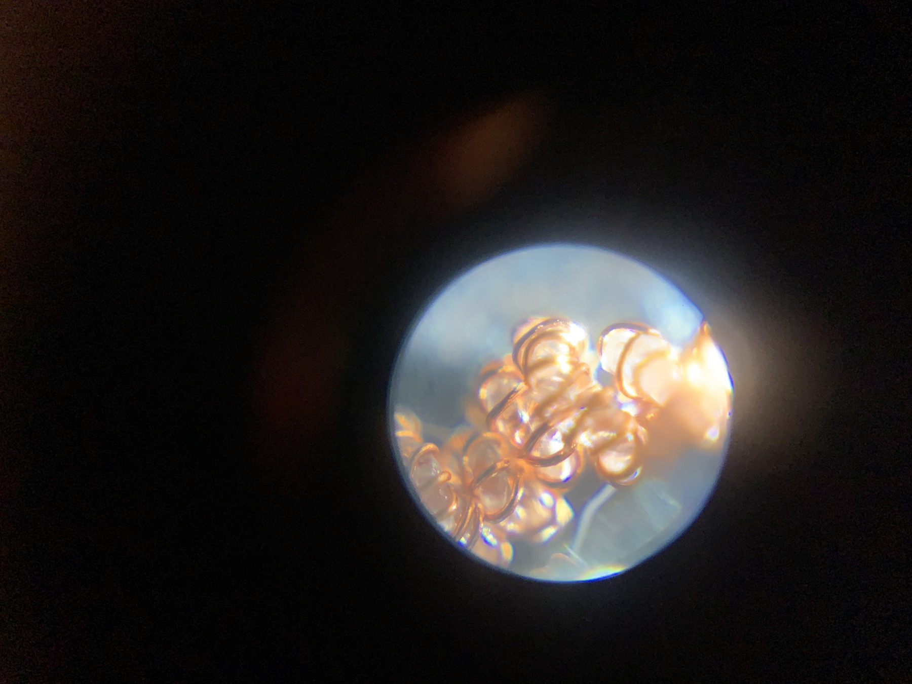
A representative specimen went from about 195mm of precursor to roughly 35–50mm of supercoil. Winding that supercoil around a blunt drill bit about 1mm in diameter produced an ultracoil roughly 10–13mm long.†
The actuators were annealed in the Floodlamp Oven, generally around 150°C for twenty to twenty-five minutes. Fifty-cent coins occasionally restrained the ends during annealing to keep the specimens from sagging.
One early single-ply supercoil visibly contracted far more than I expected. My notes estimate roughly half a second to contract, two seconds to relax and more than 40% apparent contraction. I had no synchronized displacement, force, current or temperature recording, so those numbers are not performance data.
An elastic-return jig later produced more repeatable cycling. My notes put it around 0.8Hz with roughly ±5% visible movement, again without a calibrated load or displacement trace. Blowing air over the muscle made it cool noticeably faster.
I tried ultracoiling because published work had shown large force improvements from winding an already-supercoiled actuator around a mandrel and annealing it again. The group called a single twisted-and-ultracoiled nylon actuator a TUNA. To make a parallel twisted and ultra-coiled nylon actuator, or PTUNA, they individually pretwisted four nylon precursors, twisted those together in parallel, wrapped the resulting bundle in copper, drove it into a supercoil and then wound and annealed that supercoil around a mandrel. They reported that PTUNA increased load capability by 439.7% relative to TUNA, and that two PTUNAs could do similar energy-storage work to five TUNAs. (High-Performance Twisted Nylon Actuators for Soft Robots, 17 March 2025.)
Additionally, we construct the dual-level helical structure based on parallel-twisted TNAs, resulting in a 439.7% improvement in load capability.
The paper demonstrated these actuator families in paired bionic elbows, a jumping robot and a soft finger that contracted under a 2kg load while also producing controlled bending and twisting.
At my smaller scale, the first ultracoil was mechanically stiff and electrically easy to destroy. It moved slightly, then burned open when I increased its drive voltage and pulse length without having logged its resistance, current or temperature.
The ultracoil experiment was inconclusive. My tiny specimen and drive method were not controlled well enough to tell whether the geometry worked.
Multi-ply Actuators
Single-ply fibres produced visible motion, but Wisp would need usable force. The obvious next step was combining several nylon strands.
I printed separate holders and twist-head adapters for two- and three-ply precursors. Each strand was pretwisted, the strands were parallel-twisted together, and the resulting bundle was copper-wrapped before supercoiling.
Two-ply fabrication worked a handful of times. Knots, unequal strand lengths and off-axis rotation made it less forgiving than the single-ply process, but the machine could complete it.
Three-ply fabrication exposed a more serious failure. When the composite reached its supercoil nucleation point, it could snap into the coiled state with enough mechanical violence to break the 0.05mm copper wire. That failure happened repeatedly. I believe one three-ply sample survived fabrication, but I did not electrically or mechanically test it.
Multi-ply bundles looked like the most direct route to greater force, but the stronger precursor was also capable of destroying its own conductor.
That conductor-fracture problem, the difficulty of controlling initial tension and the growing friction around annealing and extraction were the main reasons I parked the work in September 2025.
Current State
I could repeatedly pretwist fine nylon, wrap it in 0.05mm copper, form supercoils and make electrically actuated specimens with visible contraction.
I did not produce a fully measured actuator recipe. The machine had no load cell, motor-current sensing, automatic resistance measurement or specimen-temperature measurement. I deliberately used the same approximate starting length and tuned the process empirically, accepting failed specimens while I established whether fabrication at this scale was possible.
The next controller is designed around bounded motion, heartbeat shutdown, explicit faults, telemetry and a 50Hz non-blocking state machine. It measures initial nylon tension instead of assuming it. The proposed method is to pluck the loaded precursor, estimate its fundamental frequency and infer initial tension from the string equation. That controller exists in software but has not yet been commissioned on the hardware.
For now, the older machine and its scripts are still what actually makes the actuators, and they still need the same hands-on supervision they always did.
By the time the project paused, I knew I could make tiny artificial muscles. I still needed to measure the initial tension, force and stroke from each ply count, the cooling time under load, and how to stop a stronger multi-ply precursor from snapping its own conductor.
Twister turned an idea about a tiny aircraft into a fabrication process, then gave me specific failures to measure next.
Future Thoughts
As of July 2026, while typing this up, I do not expect to build another Twister for the foreseeable future. The current machine can make a supercoil in roughly six minutes without the copper-wrapping step, or about fifteen minutes with copper. I want to find out whether the conductor can be added after the mechanical forming is finished.
The PTUNA paper used 0.5mm nylon precursors and 0.16mm copper. My nylon was 0.15mm. When every linear dimension of an object doubles, its surface area grows by four while its volume grows by eight, so reducing the precursor diameter improves the surface-area-to-volume ratio available for cooling. Under the small loads I actually tried, my muscles generally relaxed in roughly three to five seconds and did not produce much useful force. These were bench observations rather than instrumented measurements. I want to compare bundles of many small supercoils with PTUNA-like multi-ply muscles, then test conductors applied after forming.
While working on Twister, I bought milligram scales and obtained a PASCO force meter so that I could characterise the finished muscles. The specimens were not reliable enough for a useful performance table. At this scale I was still struggling to keep the 0.05mm copper continuous through supercoil formation, and the published work pointed towards parallel-twisted multi-ply assemblies. Those specimens were also the most likely to snap their copper before I could test them.
My July plan was to remove copper wrapping from fabrication, plate completed supercoils and parallel-twisted assemblies in batches, then characterise the repeatable plated muscles with the scales and force meter.
- Tollens-family electroless silver. Plate the completed muscle after forming it. That removes the copper carriage, pitch and sag from fabrication, replaces the circle-to-circle contact between the copper and nylon with a near-conformal heater, and keeps the hair-thin wire out of violent multi-ply supercoil formation. Finished muscles could be loaded onto hooks in batches and moved through cleaning, activation, fresh silver and rinse baths. Holding the muscles under slight extension between the hooks would open the turns enough to reduce capillary wicking between them and let the solutions and rinse reach more of the surface. If the coating works, the same station could plate many parallel-twisted assemblies at once. I have a spare rescued Ender 3 Pro that could become the motion platform for that process.
- Conductive coatings more broadly. The processes I have been working from either wrap the nylon in magnet wire roughly one-third of its diameter, or begin with nylon that has already been plated and then damage that coating during intense pretwisting and supercoiling. I want to compare conductors applied to the finished muscle instead: resistance, adhesion, added mass, heating uniformity, cooling rate and survival through repeated cycling. Silver paint is the quickest control before committing to an electroless process.
- Parylene C. If a surface-silver heater works, adjacent turns and bundled muscles may short against one another. A thin Parylene coating could isolate and protect the conductor. It would also add thermal resistance and would have to survive repeated cycling, so I would test it after the silver works.
If the coating works, I can keep the current Twister for making supercoils, load them onto a common fixture, and add the fragile conductor after the violent forming step is over.
Documentation
Control code: twister_control.
† A photograph records roughly 200mm between the homed heads and a precursor about 195mm long. The later 35–50mm supercoil and 10–13mm ultracoil dimensions remain reconstructed from my notes and need to be checked against a surviving specimen.
Addendum — 12 August 2026
After looking at the process again, I will make one more three-ply PTNA before trying the coating work. I still form PTNA supercoils by hand, after pretwisting and storing three separate strands, so the three-ply process is much more demanding than a single-ply run. I will slow the transition down and record it. I may also tune the relative motion of the two heads over time so the machine forms the supercoil itself very slowly. If the copper survives, I will anneal and characterise the PTNA before trying the PTUNA ultracoil. If it breaks again, I will consider applying the conductor after forming.